Diese Seiten sind unsere internen Protokolle aus dem Labor.
Aufgrund der fortlaufenden Protokollierung der Ergänzungen sowie der Verbesserungen ist die Reihenfolge / Chronologie der Seiten aus dem Ruder gelaufen - leicht durcheinander geraten.
.
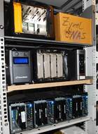
In unserem Labor haben wir drei NAS-540/542 Testsysteme
Unseren seit Feb. 2021 laufenden NAS-542 Server fassen wir nicht an !!!! Die vier NSA-320 laufen auch unverändert.
Unsere drei NAS-Test- Server 540 und 542 unterscheiden sich nur sehr gering. Beide benötigen die 19 Volt (steht hinten drauf) und werden aus dem gleichen externen (Notebook-) Netzteil mit 19 Volt (mit bis knapp 5 Ampere) versorgt
Die beiden hätten laut Internet-Infos unterschiedlichen CPUs (in einem speziellen SoC) :
- NAS-540 = Freescale (anfänglich) FS1024 dual-core @ 1.2 GHz
- NAS-542 = Freescale ARMv7 Cortex-A9 dual-core @ 1.2 GHz
("Freescale" ist die ehemalige Motorola Halbleitersparte) - Das stimmt für unsere vie Server - die beiden NAS-540 und die beiden NAS-542 NICHT !!!. Beide Typen haben den Freescale ARMv7 "SoC" mit dem Cortex-A9 dual-core und 1.2 GHz. Warum stimmen die Angaben im INternet nicht mehr ? Vermutlich wurde das in 2018 (für die europäischen Versionen) geändert.
Beide Typen haben "onboard" ein 1 MB "spi-flash" und ein 256 MB "NAND-flash" sowie 1 GB DDR3 RAM und zusätzlich einen Slot für eine SD-Speicherkarte. - Die Angabe "Operating system = ZyXEL" stimmt natürlich nicht, es ist ein 32bit Ubuntu/Debian Derivat (wobei der Firmware-Compiler unter Ubuntu 14.04.3 amd64" laufen muß).
.
Bislang "gelernte" Hardware-Informationen bezüglich "SoC" = "System on (one) CHip"
Die Bezeichnung "SoC" beschreibt einen Silizium-Chip, auf dem nicht nur die eigentliche CPU drauf ist, sondern die ganzen Peripheriebausteine, die früher bei unserer anfänglichen PC-Technik alles einzelne Chips waren. So hatten die ersten CPUs nebendran einen Floatingpoint Prozessor und eine Süd-Brücke und eine Nord-Brücke mit all den Anschlüssen. So nannte man das damals.
Der "SoC" von FreeScale (ehemals Motorola) hat neben der ARM7 (Cortex-A9) CPU ein ROM sowie ein eigenes (kleines) SRAM, dazu den Speicher-Controller, den Festplatten-Controller und die Netzwerk- und sonstigen peripheren Bausteine - alle auf diesem einen Chip - (darum auch "System on Chip").
.
Aus dem Zyxel Forum zusammengesucht :
Zu einem Kommentar zum Boot-Prozess von "Mijzelf" : Was ist in dem 256 MB großen NAND-Flash-Speicher ? - Es gibt bis jetzt noch keine Informationen darüber, daß es zusätzlich einen spi-flash Chip und diesen NAND-flash Chip gibt.
Aus dem "bootlog" liest er die folgenden Partitionen und Speicherbereiche des gesamten Flash-Speichers (also beide Chips gleichzeitig) aus :
.
| [3.331725] | 0x000000000000-0x000000040000 : | "uloader" | Partition-size | 256 kB |
| [3.343188] | 0x000000040000-0x0000000c0000 : | "barebox" | Partition-size | 512 kB |
| [3.359381] | 0x0000000c0000-0x000000100000 : | "env" | Partition-size | 256 kB |
| [3.544045] | 0x000000000000-0x000000a00000 : | "config" | Partition-size | 10 MB |
| [3.555619] | 0x000000a00000-0x000001400000 : | "kernel1" | Partition-size | 110 MB |
| [3.571391] | 0x000001400000-0x000008200000 : | "rootfs1" | Partition -size | 10 MB |
| [3.593877] | 0x000008200000-0x000008c00000 : | "kernel2" | Partition-size | 110 MB |
| [3.610057] | 0x000008c00000-0x00000fa00000 : | "rootfs2" | Partition-size | 10 MB |
| [3.621849] | 0x00000fa00000-0x000010000000 : | "reserved" |
.
In der Liste sind die Größenangaben von Hand ergänzt.
.
Der "boot" Loader und Textteile aus den Kommentaren :
Info und Vorschlag im Falle eines Fehlers beim "booten" :
If one of the Partitions 1 (uloader) and 2 (barebox) get damaged, the box might be beyond repair. But you'll never know, the "uloader" partition is big enough to be (or contain) a complete "u-boot" loader - so beschreibt es der Spezialist.
.
And the first 3 partitions are on the "spi flash". That is a tiny little 6 pin chip on the motherboard, and it seems to be possible to reprogram it without de-soldering it using an arduino.
The 3. partition (env) is important. It contains the "barebox environment". Without it the box would not boot, but "barebox" will start and give you a (command-line) prompt. It also contains the flash partition table (as command-line argument for the Linux boot).
The 4. partition (config) is not important. It contains the user settings and is erased on a factory reset. As the whole thing is about 256 MB, I did simply backup "mtd0 - mtd8". Better safe than sorry. ("mtd" wird später noch erklärt.)
.
Aber warum gibt es einen zweiten Boot-Loader ?
Erst später habe ich dann gelesen, nachdem ich gelernt hatte, daß sowohl "u-boot" als auch "barebox" beides vollständige autarke bootloader sind, daß die beiden boot-loader sich "fast" nicht unterscheiden. Also warum dann zwei ? Des Rätsels Lösung kam später. Es gibt (nur) einen "primary bootloader" PPL in dem cortex-A9 Chip und "auch nur" einen "secundary bootloader" SPL, das ist unserem Fall der NAS 540/542 die "barebox" Variante, und eben nicht der "u-boot" Loader (auch wenn die Partition so heist).
.
Wie verläuft ein Boot-Prozess im embedded System ?
Gefunden :
When we talking about boot from eMMC/SD/U-Disk/net, they are in different concept: (uns interessiert nur Version 1)
.
- Stage 1 is always in boot rom or prom (im SoC), it loads stage 2 and may load stage 3 (when SPL_BACK_TO_BROM option enabled).
- Boot from "spi-flash" means firmware for stage 2 and 3 (SPL and u-boot oder barebox only) in spi-flash and stage 4/5 in other place (bei uns im NAND-flash);
.
Das gehört dazu - Der "Boot-FLow" :
| Terminology | Shortcut | Image name | Location | |
| Boot-Stage-Nr1 | "Primary Program Loader" | (PPL) | ROM code | SOC BootRom |
| Boot-Stage-Nr2 | "Secondary Program Loader" | (SPL) | barebox - TPL/SPL | idbloader.img |
| Boot-Stage-Nr3 | barebox - ATF/TEE | u-boot.itb ? | ||
| Boot-Stage-Nr4 | kernel | linux boot.img | ||
| Boot-Stage-Nr5 | rootfs | rootfs.img |
.
Weitere Infos zum Boot-Prozess -
A little word about the boot process.
Im Zyxel Forum wird es von "Mijzelf" erklärt:
(1) A little word about the boot process. In the listing above you can see that the flash address for partition 4 = "config"' starts over at (beginnt aufs neue bei) "0000". (Anmerkung : Das wird mit einem 1 MB offset auf eine Adresse oberhalb der spi-flash- Adressen hochgeschoben)
(2) The reason is, that the "SoC" (also der in einem kombinierten Universal-Chip verbaute ARM-Prozessor) cannot boot from the 256 MiB Nand-chip (die Erklärung kommt weiter unten), so ZyXEL added a 1MiB "spi-flash"-chip. The cpu automagically reads (und zwar seriell ! ) and executes the first (256 Kilobytes) from the spi-flash-chip, that is partition "uloader".
(3) "uloader" with the "barebox" software knows where to find and to boot the raw kernel aus dem spi-flash. Der "barebox" botloader contains drivers (as for harddisks) for the "Nand-flash". It reads it's die 3. Partition 'env' (environment), which contains the location of boot-script(s), which tells to load the Linux kernel from a certain Nand-flash partition ('kernel1' or 'kernel2'), and boot it with certain command lines.
Hier zwei erklärende Links zu den Begriffen - zu den beiden loadern "u-boot" und "barebox"
https://www.deditec.de/media/manuals/.........
https://www.barebox.org
https://www.barebox.org/doc/latest/index.html
https://thenewstack.io/bootloaders-for-embedded-linux-systems/
.
(4) Linux boots (und das ist mißverständlich erzählt - es ist ein kleiner bootloader mit Kommandozeilen Interpretation), reads it's command line (which you can find in the bootlog), from which it extracts the flash partition table.
(5) It detects & initializes all hardware from which it has the drivers build in (es sind da nur die wirklich von der jeweiligen speziellen Hardware benötigten Treiber drin), and finally it executes the "init"-executable (die "/init" Datei in seinem virtuellen bootloader "root"), which is responsible for all further configuration/startup. The "/init" keeps running. It's pid 1 (die program ID 1) and if you kill it, the box shuts down.
.
Warum NAND- und/oder spi-flash-Speicher und kein E-EProm ?
Im Abschnitt oben drüber wird auf eine trickeiche Methode verwiesen, warum der 1 MB große Adressbereich (ganz am Anfang des 256 MB NAND-Flash-Speichers) mit einem 1 MB spi-Flash-Speicher "überlagert / überlappt" wird (beide ab der Ur-Adresse 0000).
Die Erklärung :
"NAND-flash" is an improvemnent over NOR-flash and is used for high density data storages. - NAND-flash interfaces are similar like interfaces in hard-drives (brauchen also einen eigenen Block-Treiber).
.
"spi-flash" stands for "serial peripheral interface". It’s a Flash Memory with a simple serial protocol that can talk to a variety of devices, including serial flash devices. "spi" is for interfacing to slow peripherals. Which, plausibly, makes it simpler.
Weiterhin kann man "spi-flash" (hier zum Beispiel die Partition "env") erheblich öfter "beschreiben" als E-Eproms, die dafür nicht geeignet sind. Und bei NAND muß man immer einzelne größere 128er Blocks am Stück "blockweise" beschreiben. Das ist vom Programm her sehr aufwendig.
.
Ein Blick in die Partitionen des spi + NAND-Flash-Speichers
Das erste Megabyte ab Adresse 0000 kommt noch aus dem "spi-flash" :
die korrekten "spi_partitionen" =
(1) 256k (uloader) ro,
(2) 512k (barebox) ro,
(3) 256k (env) das ist r/w
aus dem 256 MB NAND (nand_device=comcertonand) Chip kommt (korrigiert) :
(config):10M
(kernel1):110M
(rootfs1):10M
(kernel2):110M
(rootfs2):10M
(reserved)
.
Die hier gelisteten Informationen über die Aufteilung der Partitionen von spi und NAND sind hier inzwischen korrigiert.
.
The "Memory Technology Device" (MTD) interface :
Im Zyxel Forum kommt recht oft die Abkürzung "MTD" vor. Was ist das ?
The "Memory Technology Device" (MTD) interface is a way of abstracting flash devices as if they were normal block devices (also wie auf einer Diskette oder Festplatte). With the densities of these flash chips increasing (heute schon deutlich über 256 MB), the need for partitioning is becoming more apparent. Unlike typical block devices, however, these flash devices generally lack a partition table. Instead, they rely on the underlying operating system to enforce these partitions.
For some devices, you can specify the partition table in the kernel, typically in the board-specific file. However, not all types of MTD support this (DataFlash is one such example), and you may require more flexibility in your partitioning. This is where command line partitioning comes in.
.
Die aktuellen Partitionen unsere NAS-542 SPI- und NAND- Flash-Speicher nochmal auslesen :
[NAS-542-01 - root] / $ cat /proc/mtd
.
- dev: size erasesize name
- mtd0: 00040000 00010000 "uloader" (spi-chip ro)
- mtd1: 00080000 00010000 "barebox" (spi-chip ro)
- mtd2: 00040000 00010000 "env" (spi-chip r/w)
- mtd3: 00a00000 00020000 "config" (ab hier auf dem NAND-chip)
- mtd4: 00a00000 00020000 "kernel1"
- mtd5: 06e00000 00020000 "rootfs1"
- mtd6: 00a00000 00020000 "kernel2"
- mtd7: 06e00000 00020000 "rootfs2"
- mtd8: 00600000 00020000 "reserved"
- mtd9: 06406000 0001f000 "ubi_rootfs1"
- mtd10: 0045c000 0001f000 "ubi_config"
.
Meine (korrigierte) Interpretation des bisher gelesenen Textes:
Diese Cortex-A9- CPU in diesem "SoC" Chip (einem "System on Chip") kann ihren Flash-Speicher (mit dem Boot-Loader barebox mit der im eigenen SoC-Prom abgespeicherten (Minimal-) Intelligenz (als PPL bezeichnet) nur seriell aus einem spi-flash ab Adresse 0000 auslesen.
Denn der "SoC" kann den 256 MB großen NAND-flash Speicher jetzt noch nicht ansprechen, den dafür notwendigen Block-Treiber (für einen NAND-Flash-Speicher) muß er erst noch laden (und dieser Treiber ist erst im 2. bootloader-Teil, dem SPL). Diese Informationen kommen auch aus "uloader" samt dem Block-Treiber mit dem barebox- Loader - alles aus dem spi-flash-Speicher.
.
So weit bin ich bislang gekommen. Ob das alles stimmt ? Darum springen wir hier zum INIT Script.
.
2 große Dateien im NAND-Speicher fallen auf :
Ist das NAS-System (später) endlich hochgefahren, gibt es für openSuse-Admin in der ausgepackten RAM-Disk ein ungewöhnliches Verzeichnis "firmware" (und noch zwei weitere wie "i-data" und "e-data"), mit dem man in den NAD-flash-Speicher (sowie später in die Festplatten und USB-Sticks) "rein schaun" kann.
In dem Verzeichnis "/firmware/mnt/nand" gibt es die Datei "sysdisk.img.gz" mit 52 MB Größe und in "/firmware/mnt/sysdisk" gibt es die Datei "sysdik.img" mit 159 MB Größe. Eigentlich passen die in keine der 6 oder 8 oder 10 Partitionen rein.
.
.


